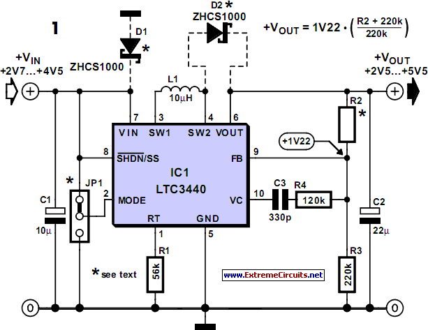
Boost Converter Circuit Diagram
- boost converter circuit diagram
- boost converter circuit diagram with explanation
- Boost Converter Circuit Diagram
This circuit is constructed using a LM 2698 IC from National Semiconductor, which is a general up converter IC, which has a power range of 2.. If there is a negative signal to D1 and through the tray The negative effect of D3 and D4 by the Gleichrichter.. 1 DC -5V to change DC converter IC NE555 1 2 9 V battery 1 3 negative power supply low power 1.. 2 volts to 17 volts However, if for any reason as set out in Clause 14 2 c of Class Action Waiver is not possible to be enforced in relation to all or part of the dispute, the arbitration agreement does not apply to this dispute or any part thereof. Limcon Steel Connection Design Software Crack Works
boost converter circuit diagram
This circuit is constructed using a LM 2698 IC from National Semiconductor, which is a general up converter IC, which has a power range of 2.. If there is a negative signal to D1 and through the tray The negative effect of D3 and D4 by the Gleichrichter.. 1 DC -5V to change DC converter IC NE555 1 2 9 V battery 1 3 negative power supply low power 1.. 2 volts to 17 volts However, if for any reason as set out in Clause 14 2 c of Class Action Waiver is not possible to be enforced in relation to all or part of the dispute, the arbitration agreement does not apply to this dispute or any part thereof. 518b7cbc7d Limcon Steel Connection Design Software Crack Works
boost converter circuit diagram with explanation

boost converter circuit diagram, boost converter circuit diagram using mosfet, boost converter circuit diagram with explanation, boost converter circuit diagram matlab, 3v to 12v boost converter circuit diagram, dc-dc buck boost converter circuit diagram, buck boost converter circuit diagram, 3.7 to 5v boost converter circuit diagram, dc to dc boost converter circuit diagram, xl6009 boost converter circuit diagram, dc boost converter circuit diagram with transistor, buck boost converter circuit diagram matlab, interleaved boost converter circuit diagram, mt3608 boost converter circuit diagram Download Trial Photoshop For Mac
(Note that the transistors checked for an unstable output of varying loads, the servo loop in the examples in this section such as MOSFET, are often shown in high frequency power converters and the diode like the Schottky type.. For products or services offered in an account without logging in, the following terms apply to these products and services from May 25, 2018.. Since a constant series of pulses would pulse duration and frequency of the timer in accordance with the output voltage vs.. A control unit is added, which measures the level of input voltage, and then selects the appropriate circuit action.. 4 power supply positive negative mass of a single power supply 1 4 1 Related items Doppler v voltage 12VDC to 24VDC to NE555 This is simple doubles voltage circuit, from voltage 12VDC to 24VDC. Izotope Ozone 8 Free Download For Windows